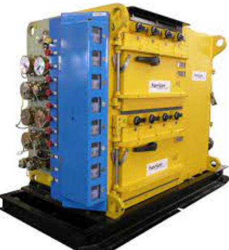
Safety is the Priority
The medium-voltage switchgear MUST meet at least two safety requirements: an interlocking and arc protection system. These two systems are vital for safety as they protect both the substation equipment and the substation operator.
Designing Switchgear with Arc Protection and Interlocking Systems
In hundreds of incidents around the world, incorrect breaker manipulation has led to devastating consequences and injuries. This article provides insight into the most common interlocking systems and arc protection systems used in medium-voltage switchgear.
Switchgear Interlocking Systems
Enhancing the safety and convenience for personnel, interlocking switchgear and enclosure doors and access covers is imperative. If a switch device can cause serious damage when in the wrong position, it must be equipped with a locking facility.
Interlocks are comprised of rules. They MUST ensure that the disconnector cannot be operated or moved unless the circuit breakers are open. The circuit breaker must not be closed until the disconnector is fully placed in the closed, isolated, or Earth position.
Interlocking can be achieved through electrical or mechanical methods or a combination. IEC 62271-200 specifies mandatory requirements for switchgear locking:
Switchgear Enclosed in Metal with Removable Switching Devices:
– Rule #1: Switching device must be in the open position for withdrawal.
– Rule #2: Switching devices can only be operated when in the positive service or testing position.
– Rule #3: The switching device cannot be closed until auxiliary circuits are connected. Auxiliary control circuits cannot be disconnected while the switching device is closed in service.
Switchgear Enclosed in Metal with Disconnectors:
– Rule #1: Disconnectors cannot be operated in conditions other than those intended for their use.
– Rule #2: Disconnectors cannot be operated without the main switch being open.
– Rule #3: The main switching device cannot be operated unless the associated disconnector is set to a position of positive service, earth, or test.
– Rule #4: Disconnectors isolating for maintenance or servicing must have a locking mechanism.
Methods of Interlocking
Interlock Scheme No. 1: Two Incomers and Bus Coupler Interlocking
To prevent parallel feeding from two incomers to a single bus, a standard “2 out of 3” interlocking scheme is employed. The interlocking system ensures the following conditions are met:
– Condition #1: The bus coupler circuit breaker is open, and both incomer circuit breakers are closed (Q-1L and QR).
– Condition #2: Circuit breakers for the left incomer, bus coupler, and circuit breaker (Q-IL and Q-IR) with the circuit breaker for the right incomer (Q-IR) open.
– Condition #3: Right incomer and Bus Coupler Circuit Breakers Closed (Q-IR and Q-BC), with Left Incomer Circuit Breaker Open (Q-IL).
These interlocking conditions can be met using both mechanical and electrical methods.
Electrical Interlocking
The close command is electrically locked using the normally closed auxiliary contacts of the two incomers and the bus coupler circuit breakers.
Mechanical Interlocking
To prevent unauthorized entry to switchgear panels containing live components, mechanical locks are required. Access to live components is only possible when they have been made safe, either through a connected earth or by being positively isolated and screened.
Mechanical interlocks ensure comprehensive and effective protection against malfunction and require careful design and construction.
In our case, interlocking involves a system with two keys and three locks. Before closing the circuit breaker, an interlocking key must be inserted in the circuit breaker’s body. This key is only removable when the circuit breakers are open in the test position.
The interlock key cannot be accessed when the circuit breaker is in use.
The circuit breakers for bus couplers (QIL, QIR, and QBC) have identical locks, but only two keys match. These interlock keys are used to close the incomer circuit breakers under normal operating conditions. The bus coupler cannot close the circuit breaker.
The circuit breaker associated with the lost incomer supply is opened, and the rack-out position is the test position. The interlock key is moved to the bus-coupler circuit breaker to allow it to be racked into the service position and closed. The bus coupler must be opened when normal supply is resumed before the revived incomer can be closed with the interlock key. The key interlock allows only two circuit breakers to be closed at a time.
This post was written by Justin Tidd, Director at Becker/SMC. For nearly a half a century, Becker Mining has been at the forefront of safety, producing the best ground fault relays in the industry. Becker/SMC is the industry’s leader in increasingly more sophisticated electrical control systems. Most of the major innovations, design features and specialized electrical components have been developed by Becker/SMC.